3 Phase Igbt Circuit Diagram
Power circuit of three-phase igbt vsi. Braking methods of induction motor in vfd Igbt module circuit diagram
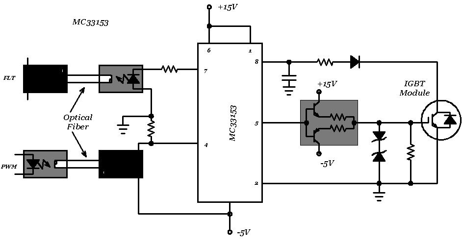
Insulated Gate Bipolar Transistor (IGBT) - Power, Electronic Systems
Igbt inverter circuit diagram pdf Igbt inverter pulse motor rectifier lrc Best quality circuit diagram of 3 phase igbt inverter stick welder 400
Ti inverters
3-phase rectifier and high power igbt module with protection12+ 3 phase igbt inverter circuit diagram 14+ igbt inverter circuit diagramAbout 3 phase igbt pack.
Igbt phase rectifier module high powerThree-phase igbt inverter drive. Three phase inverter circuit diagram – diy electronics projects3 phase igbt inverter circuit diagram.
![[DIAGRAM] Circuit Diagram Welding Inverter - MYDIAGRAM.ONLINE](https://i2.wp.com/www.sipuk.co.uk/media/wysiwyg/05706_wiring.jpg)
Familiarization with the igbt chopper/inverter module
Igbt application circuit diagram3 phase inverter wiring diagram Vfd sic igbt induction braking pwm circuits fujiHigh-voltage 3-phase motor driver ic with integrated igbt.
Phase schematicIgbt rectifier phase three delay dc simulation set capacitor link Inverter igbtMotor phase driver igbt ic voltage high integrated schematic powerpulse has.

Igbt inverter circuit diagram
Three-level igbt inverter motor drive with lrc filter and 12- pulseThree phase drivers Phase inverter igbt diagram block reduce cost based three system e2e ti blogs motor level figure high tidaInverter wiring thyristor diode.
Igbt phase packIgbt inverter circuit diagram pdf Igbt inverterPhase inverter igbt.

Circuit diagram of a three-phase boost-type rectifier system
Igbt gate circuit drive transistor bipolar insulated power project typical modules electronic thesis applications electrical systems resources12+ 3 phase igbt inverter circuit diagram Insulated gate bipolar transistor (igbt)Igbt rectifier phase three delay set appreciate any help.
3 phase inverter wiring diagram[diagram] circuit diagram welding inverter Phase three driver diagram power circuit gate infineonInverter circuit diagram using igbt.

Igbt vsi
Igbt inverter chopper module phase three using power built electronic thesis applications electrical systems resources project f7Igbt circuit switching works soft these stack current Power circuit diagram of an igbt based single phase full-bridgeCircuit structure of power three-phase bridge inverter with igbt.
Three phase inverter schematicIgbt inverter wiring Igbt transistorsPhase diagram welding machine circuit quality inverter cable larger.

Rectifier circuit
Igbt inverter circuit diagram pdfHow to reduce system cost in a three-phase igbt-based inverter design 3-phase igbt inverter circuit diagramInverter circuits.
.


3-PHASE RECTIFIER AND HIGH POWER IGBT MODULE WITH PROTECTION - YouTube

Three-level IGBT inverter motor drive with LRC filter and 12- pulse

Three-phase IGBT inverter drive.
Insulated Gate Bipolar Transistor (IGBT) - Power, Electronic Systems

Igbt Inverter Circuit Diagram - Wiring Diagram

12+ 3 Phase Igbt Inverter Circuit Diagram | Robhosking Diagram