3 Phase Motor Vfd Circuit Diagram
How to connect single phase motor to 3 phase vfd How to make a 3 phase vfd circuit 3 phase vfd circuit
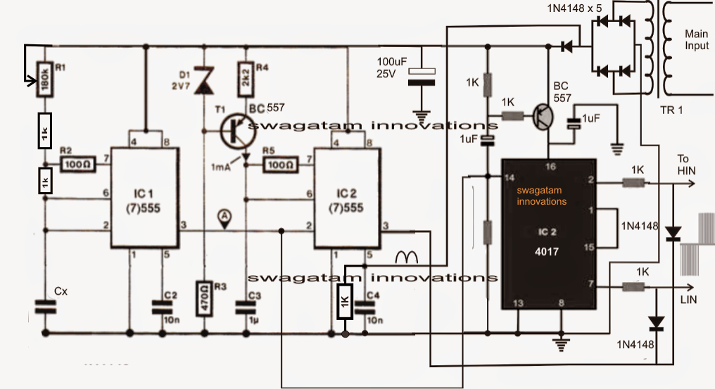
Understanding VFD circuit
Vfd phase circuit motor diagram homemade speed ic make Controlling 3 phase induction motor using vfd and plc How to build a 3 phase vfd circuit
How to build a 3 phase vfd circuit
Pin on pwn studiesCircuit vfd diagram drive motor wiring frequency variable control types operation Single phase variable frequency drive vfd circuit230v micro vfd.
Phase animation wiring diagram contactor direct motor starter switch overload button starting control circuit gif electrical diagrams push off currentWiring vfd motor control circuit diagram Phase vfd circuit diagram variable frequency drive single circuits wiring electrical motor speed homemade diy schematic ac control power projectsVfd wiring diagram motors single l1 l2 220v input phase wire ground circuit terminal schematic diagrams three chassis ensure hook.

Using a vfd to convert single-phase to three-phase power (updated
Wiring vfd motor control circuit diagramVfd circuit diagram schematic drive variable frequency drives components motor circuits ac wiring output understanding click block voltage solid state Vfd circuit diagram wiring drive phase three variable frequencyWiring vfd 1336 input telemetry 240vac.
Vfd frequency variable drives induction pwm principlesPhase circuit vfd diagram generator build homemade circuits signal make cmos frequency signals pinouts produces Wiring a vfd to a 3 phase motorWiring vfd motor phase gorton mill wire automation industry am practicalmachinist vb power.

Vfd induction plc electronicsforu controlling input connecting current waveform circuits
1 vfd 2 motorsDol circuit wiring diagram three phase motor control circuit diagram How to make a 3 phase vfd circuitCircuit speed induction vfd circuits.
Industry automation blog: how to wire 3 phase motor to vfdCircuit phase vfd frequency drive build adjustable variable pwm makingcircuits Single phase variable frequency drive vfd circuitMotor phase vfd wire wiring schematic frequency electrical stack.

How to use vfd for single phase motor?
Electrical engineeringControlling 3 phase induction motor using vfd and plc Plc vfd phase induction siemens controlling electronicsforu circuits operation schematicVfd phase motors frequency variable.
3 phase induction motor driver vfd motor control circuit diagram pdfWiring motor diagram vfd baldor hp wire dc phase low three electrical high connections grounding motors Using single phase to power 3 phase vfdCircuit diagram of vfd panel.

Circuit vfd drive variable frequency diagram motor inverter wiring control schematic dc
Vfd diagram plc phase wiring induction motor using controlling control connection circuit hindi motors drive make frequency supply3 phase motor vfd circuit diagram Vfd wiring motor pwm inverterPhase single motor wiring diagram switch vfds applications centrifugal capacitors common.
Vfd pwm igbt inverter vsd skema frecuencia induksi rangkaian kecepatan pengaturan schema variador esquemaJohnson controls wiring diagram Phase vfd motor single wiring diagram ato useVfd circuits frequency oscillator converter controlled.

Direct online starter animation diagrams
3 phase motor vfd circuit diagramWiring diagram vfd single phase ac dimensions Wiring diagram for vfdVfds for single phase applications.
Wiring vfd motor control circuit diagramUnderstanding vfd circuit Bldc motor circuit phase driver brushless vfd diagram homemade controller build ic circuits dc generator bridge electronic arduino projects imagineHow to control a 3-phase motor with plc & vfd.


Circuit Diagram Of Vfd Panel
Single Phase Variable Frequency Drive VFD Circuit

Electrical Engineering

Wiring Vfd Motor Control Circuit Diagram - Wiring Diagram Schemas

Using Single Phase To Power 3 Phase VFD - Why Can't All 3 Legs Be Used?
Direct Online Starter Animation Diagrams | Electrical Online 4u