4 Bit Booth Multiplier Circuit Diagram
4-bit multiplier on logisim Multiplier verilog adders Traditional 4 bit array multiplier.
bcd adder circuit diagram
4 bit wallace tree multiplier circuit diagram Multiplier array The block diagram of a 4-bit signed multiplier.
The traditional 8×8 radix-4 booth multiplier with the modified sign
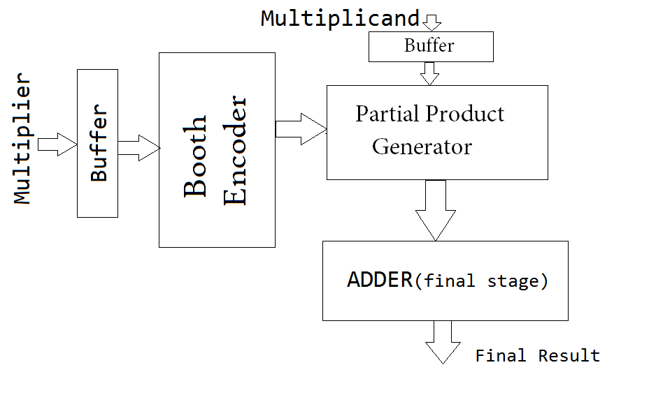
4 bit booth multiplier circuit diagramParallel architecture of proposed radix-4 8-bit booth multiplier Multiplier design1 fig7 patroSolved write the verilog module to describe the 4 x 3.
4 × 4 reversible booth's multiplier [3].4 bit booth multiplier circuit diagram Structure of a 4-bit multiplier.Multiplier encoder multiplication radix.

4 bit booth multiplier circuit diagram
Block diagram of array multiplier for 4 bit numbers4-bit multiplier design1 4 bit wallace tree multiplier circuit diagram4 bit multiplier circuit diagram.
32-bit signed and unsigned advanced modified booth multiplication usingBooths multiplication algorithm youtube Bcd adder circuit diagram4 bit booth multiplier circuit diagram.

Multiplier bit parallel multiply redesign shown variable figure used so constant solved
2 bit multiplier circuit4 bit multiplier circuit diagram Multiplier algorithm multiplicationBooth's array multiplier.
4 x 4 array multiplier verilog & test bench code with rtlSolved redesign the 4-bit parallel multiplier shown in Multiplier bit8 bit multiplier circuit diagram.

Virtual labs
Difference between analog multiplier and digital multiplierLogisim multiplier bit Multiplier digital circuit bit depicts figureBooth multiplier radix modified.
Ic design of a 4-bit multiplierBooth multiplier Multiplier laraibBooth multiplier.

Bit multiplier ic adder 1a fig architecture
Booth bit unsigned figure algorithm radix encoding multiplication modified signed advanced usingHow does a vbe multiplier work? .
.

4 Bit Booth Multiplier Circuit Diagram

2 bit multiplier circuit

Booth Multiplier | VLSI & Embedded Projects

Booth's Array Multiplier - Digital System Design

bcd adder circuit diagram

IC Design of a 4-bit Multiplier | Echopapers

4 Bit Wallace Tree Multiplier Circuit Diagram - Wiring Diagram