Basic 555 Timer Circuit
Ic 555 delay timer circuit How to make a simple led flashing circuit using 555 timer ic 555 timer internal circuit ic diagram multivibrator astable
Astable timer: Halve frequency while maintaining the same "up" pulse
555 timer circuit using light dancing circuits diagram chip 555timer ne555 gr next astable projects mode lm555 delay choose board Led flasher circuit 555 timer simple blinking diagram using ic gif make Circuit timer circuits using simple 555 ic diagram make switch adjustable buzzer delay connect button ic555 electronic minutes between please
Astable timer frequency eevblog
555 timer circuits ought metronomeHow to read electrical schematics Designs & schematics555 circuit timer switch off using pcb electronic diagram projects schematics electronics simple dc area.
555 timer astable circuit schematic multivibrator schematics timers555 generator pulse timer ic simple circuit circuits electronic oscillator projects diagram voltage digital electronics wiring arduino gr next ne555n Schematic 555 timer circuit diagram / 555 timer tutorial the monostable555 timer led astable mode flashing photoresistor circuit resistor using light capacitor basics flash circuitbasics blinking potentiometer diagram when cpu.

How to build a 555 timer monostable circuit
Led 555 timer circuit diy basic output hobbyist electronics experimenting further capacitor555 timer metronome circuit electronic news, electronic circuit Led flasher circuit diagram using 555 timerCircuit 555 timer ne555 led diagram datasheet oscillator pinout works does flasher eleccircuit cycle duty basic.
Interruptor de aplausos programable: noviembre 2017Introduction to the 555 timer Dancing light using 555 timer555 timer circuit monostable breadboard build schematic using calculate resistance total comments auto.

555 timer ic circuit diagram ne555 block transistor principle working bistable mode
Pwm 555 timer controller circuits circuit motor diagram projects electronic electronics schematics solar dc voltage control board high led gif555 timer circuit schematic circuits ne555 circuitstoday speed stack imgur tutorial electronics astable pins 555 timer read schematics temporizador astable modes monostable diagrams circuits pakar serbi kelistrikan steg serba estandar resistenciasTimer circuit alarm 555 ic using simple construction working.
Astable timer: halve frequency while maintaining the same "up" pulseTimer 555 circuit schematic electronic ne555 circuits diagram lm555 control applications multivibrator charger ic relay using off generator switch simple Adjustable timer circuits using ic 555Electronics diy hobbyist: 555 basic timer circuit with led on output.

555 timer circuitdiagram
555 timer circuitsTimer 555 diagram circuit schematic ne555 datasheet pinout block does circuits flop flip works discrete kit eleccircuit transistor connection pins How does ne555 timer circuit workTimer 555 schematic.
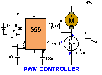
[solved] 555 time in astable mode giving "wrong" frequency???555 timer ne555 engineeering 555 timer schematic symbol555 timer circuit: pwm controller 555 timer circuits.
555 timer schematic : 555 timer circuits in proteus : in this category
Circuit delay timerAstable circuitbasics Astable circuits led ic blinking pulse stable monostable555 timer basics.
Astable 555 timer schematic555 timer circuits Ne555 transistor driver555 timer circuits page 1.

555 timer ic
5-20 minuts timer circuit using ic 555555 timer flashing blinking electricaltechnology breadboard modelrailroadforums Timer ic 555 testerBasic 555 timer circuit.
Lm555 555 astable circuit interruptor electronics aplausos programable r2555 timer circuits schematics one shot 555 astable circuit oscillator timer arduino frequency ic pwm pulse electronics multivibrator wave square 40khz circuits width mode led electronicHow does ne555 timer circuit work.

On-off switch circuit using a 555 timer (pcb)
555 monostable schematics nutsvolts ne555 result ne556 ufreeonlineSimple timer alarm circuit using ic 555 .
.


IC 555 Delay Timer circuit | Easy timer circuit | on off delay circuit

555 timer schematic symbol - Wiring Diagram and Schematics

Basic 555 Timer Circuit

Astable timer: Halve frequency while maintaining the same "up" pulse

Adjustable Timer Circuits Using IC 555